Advances in Renewable Energy (ARE)

Volume 1, Year 2014 - Pages 1-10
DOI: TBD
Waste Heat Energy Supercritical Carbon Dioxide Recovery Cycle Analysis and Design
Kevin R. Anderson1, Trent Wells1, Daniel Forgette1, Ryan Okerson1, Matthew DeVost1, Steve Cunningham2, Martin Stuart2
1California State Polytechnic University at Pomona, Mechanical Engineering Dept. Solar Thermal Alternative Renewable Energy Lab, 3801 West Temple Ave, Pomona, CA, 91768, USA
kranderson1@csupomona.edu
2Butte Industries, Inc. Burbank, CA, 91501, USA
Abstract - The US Department of Energy has estimated that 280,000 MW of recyclable waste heat is expelled annually by U.S. industries. Further estimates suggest that harvesting it could result in a savings of $70 billion to $150 billion per year [1]. Thus, any efficiency increase will result in savings to energy producers. Supercritical Carbon Dioxide (SCO2) provides unique advantages over alternative waste heat recovery systems however; it also produces unique design challenges. We propose a novel energy recovery device based on a SCO2 regenerative Rankine cycle for small-scale (1kW to 5kW) heat recovery. This study presents a thermodynamic SCO2 cycle analysis for waste heat recovery from low temperature (200°C - 500°C) sources using small mass flow rates (20 – 60 grams/sec). This paper will present a prototype SCO2 cycle architecture including details of key system components. Preliminary modeling suggests that SCO2 systems are viable for low temperature waste heat recovery applications.:
Keywords: waste heat to power, supercritical carbon dioxide, regenerative Rankine cycle, renewable energy.
© Copyright 2014 Authors - This is an Open Access article published under the Creative Commons Attribution License terms. Unrestricted use, distribution, and reproduction in any medium are permitted, provided the original work is properly cited.
Date Received: 2013-11-11
Date Accepted: 2014-03-24
Date Published: 2014-04-09
Nomenclature
- b: pump width, m
- D: diameter, m
- Dh: hydraulic diameter, m
- Ds: characteristic diameter, m
- e: effectiveness, %
- h: heat transfer coefficient, W/m^2-K, specific enthalpy, kJ/kg
- H: head, m
- k: thermal conductivity, W/m•K
- ṁ: SCO2 flow rate, kg/sec
- N: pump revolution, rpm
- Ns: specific speed, dimensionless
- P: power, kW
- pi: initial pressure, MPa
- po: final pressure, MPa
- Pr: Prandtl number, dimensionless
- Qin: heat flux into the system, W/m2
- Qout: heat flux leaving the system, W/m2
 : Energy, kW
- Re: Reynolds number, dimensionless
- SCO2: Supercritical Carbon Dioxide, kg
- s: entropy, kJ/kg•K
- si: isentropic entropy, kJ/kg•K
- t: plate thickness, m
- Tcold: cold temperature, °C
- Thot: hot temperature, °C
- VF: volumetric flow rate, m3
- w: Plate width, m, specific work, kJ/kg
- WR: Work, kJ
 : Power, kW/kg
- η: cycle efficiency, %
- ηcarnot: Carnot efficiency, %
- ξ: power coefficient, dimensionless
- ρ: density, kg/m3
- σmax: maximum stress, MPa
- φ: flow coefficient., dimensionless
- y: head coefficient., dimensionless
1. Introduction
According the American Council on Renewable Energy (ACORE) [2], there is an abundant source of emission-free power in the U.S. which is currently being overlooked. This source of power is known as waste heat, a by-product of industrial manufacturing processes which can potentially revitalize U.S. manufacturing, stimulate economic growth, lower the cost of energy, and reduce the carbon imprint due to emissions used for electricity generation. If not harnessed to generate emission-free, renewable equivalent power, waste heat is released into the atmosphere via stacks, vents, and other mechanical equipment. Waste Heat to Power (WHP) captures waste heat with a recovery unit, and converts the waste heat into electricity through a heat exchange process. WHP produces not emissions because no fuel is burned. The American Council on Renewable Energy (ACORE) estimates that there are approximately 575 MW of installed WHP capacity in the US alone, while the EPA [3] estimates that there is approximately 10 GW of WHP capacity in the U.S., enough to power 10 million U.S. homes. From the Heat is Power (HiP) Association [4], WHP is included in 15 state renewable energy portfolio standards. By using WHP to generate emission-free power, users can re-route the power back to the local infrastructure grid or sell it to the host grid in order to support clean energy production, distribution and usage. The primary technologies employed by WHP systems are Organic Rankine Cycle (ORC), Supercritical Carbon Dioxide (SCO2), the Kalina Cycle, the Stirling Engine, and other emerging technologies such as thermo-electrics. In this current paper, we demonstrate the use of SCO2 technology as a viable resource for the generation of emission-free electricity, which is clearly a renewable energy breakthrough.
Supercritical Carbon Dioxide, SCO2 has been considered a viable alternative working fluid for power cycles since the 1960s because it provides several advantages over steam and helium [5-9]. The density of SCO2 allows energy extraction devices to have a much smaller footprint than comparable steam and helium based turbo machinery [9]. Additionally, the critical point of CO2 is very low (31.1 °C and 7.4 MPa) compared to other fluids, allowing for heat transfer from low temperature (200 °C – 500 °C) sources to the supercritical state [10]. Operating in the single supercritical phase throughout the proposed cycle reduces the need for two-phase hardware [9]. However, due to the operating pressure and highly variable, non-linear fluid properties, suitable hardware for industrial use did not exist until recently [7, 8]. Advancements in compact heat exchangers and turbo machinery coupled with the drive for business to become "green" has revived interest in SCO2 power cycles leading to new solutions for energy addition and extraction [7, 8]. More recently, the investigations of [11-13] have advanced the applicability of SCO2 cycles for use in low-grade waste heat recovery. The studies of [14-17] afford comprehensive comparative thermodynamics analyses comparing the feasibility of using SCO2 for low-grade waste heat recovery. The work of [18] offers a parametric optimization study of the SCO2 power cycle for waste heat recovery maximization. The breakthrough work of [19,20] has led to the year 2013 unveiling of a 8 MW SCO2 EPS100 commercially available heat recovery system from Echogen Power Systems, LLC. Studies addressing the attraction of SCO2 cycles for other applications including Solar Thermal, Geothermal and automobile fuel consumption applications include the works of [21-25]. From the literature review presented herein, the relation of the current paper and the arena of renewable energy has been properly placed into context. The objective of this current paper is to investigate the waste heat regenerative SCO2 Rankine cycle performance and feasibility with low flow rate through mathematical modeling and to compare our results with previous findings and offer a hardware selection guidelines in the form of a novel expander device which can be used to generate electricity via a SCO2 Rankine regenerative cycle.
2. Regenerative Rankine Cycle Layout
The waste heat regenerative Rankine cycle is made up of six components as shown in Figure 1.
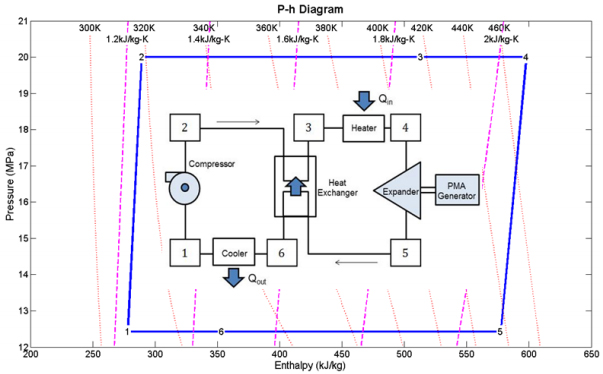
The SCO2 cycle starts at a low side pressure above 7.5 MPa and a low side temperature of 35 °C, slightly above the critical point. After compression the SCO2 is brought to the high-side pressure of 20 MPa and a temperature of 36 °C, approximately 1 °C higher than the pre-compressed state. An internal heat exchanger then heats the pressurized SCO2 by exchange with low-pressure, post-expansion SCO2. After exiting the internal heat exchanger the SCO2 is heated in a second heat exchanger where addition is done via waste heat, raising the temperature to its ultimate value of approximately 200 °C. The heated and pressurized SCO2 is then expanded near isentropically to produce rotational energy. The rotational energy is converted to electricity by coupling the expander's output shaft to a permanent magnet alternator. The fluid exits at a low-side pressure of 12.4 MPa and a temperature of 163 °C. The expanded fluid is then run through the internal heat exchanger where it is cooled by high-pressure, pre expansion SCO2. The cooled supercritical CO2 is finally passed through a radiator where it exits at the pre-compressed pressure and temperature.
The following steady-state, steady-flow thermodynamic relations given in Eqn. (1) through Eqn. (9) relate the hardware components of Figure 1 to the various operating points labeled on the p-h Mollier state diagram of the SCO2 working fluid as shown in Figure 1.
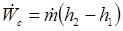
Compressor:

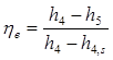
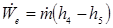
Expander:
Waste Heat:
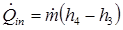
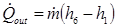
Condenser:
Specific Work Output:

Cycle Efficiency:

Heat Exchanger Effectiveness:

3. Mathematical Modeling
3.1. Cycle Analysis and Optimization
In order to determine the most efficient operating point, a parametric analysis is performed using first order thermodynamics. For the prototype cycle, limits are chosen to be 35°C and pressure above 7.4 MPa to maintain the fluid above the critical point and avoid two-phase flow. Temperature on the high side is dictated by input from a low quality heat source, which generally originates at 200 °C - 500 °C [26]. Pump and expander efficiencies are determined from assumptions outlined in section 4. The remaining fixed parameters are determined based on system requirements of recovering energy from low-quality heat using SCO2.
The three degrees of freedom considered for the parametric analysis are: volumetric expansion ratio, high side pressure, and the temperature drop across the cooler. In order to close the thermodynamic cycle the temperature drop across the cooler was assumed to be a function of all other parameters. A MATLAB program is used to vary the three degrees of freedom, discard any physically impossible cycles, then determine the most efficient parameter combination. The flow chart for this program is shown in Figure 2. In order to eliminate two degrees of freedom, the Carnot efficiency ηcarnot as given in Eqn. (10) dictates that the greatest efficiency will be achieved when Tcold is minimized and Thot is maximized. Therefore, maxima and minima for these values are selected where Tcold is above the supercritical region and Thot is lower than the waste heat source.
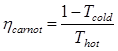
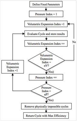
Figure 3 is generated using the same MATLAB code and shows the dynamic relationship dictated by the governing equations and boundary conditions (i.e. high-side and low-side pressure, and state-points from the p-h diagram). Using Figure 3 the required temperature drop across the heat exchanger, cooler, and cycle efficiency may be determined for a given heat exchanger effectiveness. Figure 3 can thus be viewed as a road-map in SCO2 waste heat recovery cycle component design and selection. Using MATLAB on a 64-bit workstation the one source of possible numerical error is round-off error. Herein round-off error is estimated to be 10%, which is bounded by the at least 15~20% uncertainty associated with the SCO2 thermo-physical properties as obtained from REFPROPS [10].
After our design optimization was concluded, the state points shown in Table 1 were recorded to document the optimized SCO2 Rankine Regenerative Cycle. Table 1 is an itemized tabulation of where the state points fall on the p-h and T-s phase diagrams for optimum performance of our proposed cycle. These points are tabulated in Table 1 in order to provide future guidance for researchers who desire to springboard from our current analysis. Given conservative device efficiencies an overall cycle efficiency is found to be 11% with an optimum volumetric expansion ratio to be between 1.4 and 1.5. Furthermore, to achieve this cycle the heat exchanger need only be 78% effective.
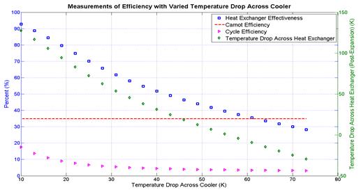
Table 1. Operating Points Defined by Cycle Optimization
| State Points | T (K) |
P (MPa) |
ρ (kg/m3) |
h (kJ/kg) |
s (kJ/kg-K) |
| 1 | 308 | 12.4 | 776.61 | 278.19 | 1.23 |
| 2 | 319 | 20 | 810.4 | 289.38 | 1.24 |
| 3 | 417 | 20 | 338.83 | 513.32 | 1.86 |
| 4 | 473 | 20 | 258.82 | 597.79 | 2.05 |
| 5 | 436 | 12.4 | 176.78 | 577.23 | 2.08 |
| 6 | 328 | 12.4 | 537.76 | 353.29 | 1.47 |
3.2. Results Comparison
These current findings are in qualitative and quantitative agreement with the studies of [11-13, 15, 16]. When comparing our current findings of 11% efficiency it should be kept in mind that herein we have assumed a nominal pinch-point in our heat exchanger on the order of 10 °C (from Figure 3) in comparison to a pinch-point of 5 °C assumed in [11,15]. A larger pinch-point translates into a smaller heat-exchanger, such as the ones physically realized by the commercial hardware of [19, 20]. Nevertheless, our efficiency of 11% for the cycle given by the state-points of Table 1 and Figure 1 agree with the findings of [15] where high-side and low-side pressures of 200 bar, and 60 bar afford an efficiency of 13%. Furthermore, our current findings agree with the high pressure limiting behavior of efficiency for SCO2 regenerative waste heat recovery cycles reported by [12, 13], where efficiencies on the order of 9% are reported for high side pressures of 150 bar. Finally, the asymptotic trends of cycle efficiency versus SCO2 mass flow rates reported in [16] asymptotically limit the cycle efficiency to 10% which is in qualitative agreement with the current findings of this paper. With the above comparison of our results to available data in the literature, the accuracy of our present calculations has been demonstrated.
3.3. Heat Exchanger Sizing
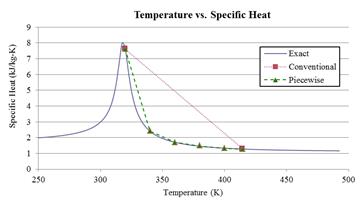
Current heat exchanger analysis techniques call for evaluation of fluid properties using bulk average temperatures. However, this assumption is only valid for fluids with properties that vary linearly within the heat exchanger. Evaluating fluid properties at the bulk average temperature severely overestimates specific heat throughout the heat exchanger [10], as shown by the "Conventional" line in Figure 4. Furthermore, there has been little research done to improve the analysis of such fluids other than computational simulations. To avoid overestimation, the heat exchangers were sized using a piecewise technique and the heat exchanger was split into dimensionless axial nodes where fluid properties varied more linearly as shown by the "Piecewise" line in Figure 4. The technique involves iteratively stepping through the heat exchanger at different nodal points. Once solved, the fluid properties are updated until error is minimized before the analysis steps to the next node. Depending on the design configuration, appropriate convective correlations were used from standard heat transfer analysis [27, 28]. This technique allows one to account for variation in fluid properties to approximate heat exchanger size without costly and time- consuming testing.
4. Component Selection
4.1. Pump
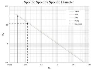
Supercritical Carbon Dioxide, SCO2 systems present not only thermal design challenges but also gives rise to special considerations for the pump. There have been multiple attempts that address the optimization of a pump for SCO2 applications [15, 29, 31, 32] that indicate an efficiency of 85% to be reasonable and conservative. Efficiency may often be increased through later optimization, however, for the purpose of this paper an 85% efficiency is assumed to determine the work required to compress the SCO2 from 12 MPa to 20 MPa. In order to determine an initial pump design the concepts of the Cordier diagram are used determine an optimal type of pump for the cycle. By comparing non-dimensional parameters such as the flow coefficient ϕ, head coefficient ψ, and power coefficient ξ a suitable speed and characteristic diameter may be calculated using Ns and Ds. Combining ϕ, ψ, and ξ allows an efficiency to be specified per η [32, 33]. Equations (11) through (16) define the non-dimensional parameters used in the turbo-machinery component selection. Utilizing these results for an 85% efficiency yields a relatively small specific speed and a large specific diameter requirement. The Cordier diagram dictates that for this combination of operating points reciprocating pump is the optimal starting choice for the compression cycle [32, 33]. This determination was also repeated for the expander selection discussed later and shown in Figure 5.


Where N is rotations per minute, Vf is volumetric flow rate of the fluid in cubic meters per second, H is effective head in meters, D< is the effective diameter in meters, P is power in Watts, and ρ is density in kg/m3.
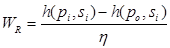
Isentropic compression assumes ideal conditions with no losses. However, losses are incurred by leaks, heat transfer between the pump and fluid, and under or over compression leads to examination of the enthalpy difference between the compression state points. The compression cycle of SCO2 occurs between state points 1 and 2, raising the pressure from 12 to 20 MPa. Work is determined as the enthalpy difference in the isentropic and polytropic compression of the fluid as shown in Eqn. (17). This analysis yields an energy requirement of 0.2 kW to raise the pressure to the 20 MPa operating condition.
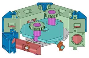
4.2. Expander
The SCO2 in the expander undergoes near isentropic expansion in order to create mechanical energy to turn a permanent magnet alternator. The initial design was a toroidal engine with opposing pistons however, this architecture was found to be too difficult to fabricate. Therefore the expander design was revised into a more linear hexagonal variation. The latest iteration of the expander design is shown in Figure 6. This type of expander was chosen over a more conventional turbine expander due to the low volumetric flow rates within the cycle and results from calculating the specific speed and specific diameter similar to the pump selection methodology shown in Figure 5. The expander alternates intake and exhaust cycles to create axial piston movement. Each bank of three pistons is attached to a mounting plate that converts axial motion into rotational motion. A cam and a gear system is implemented to output power to a permanent magnet alternator. The design is still undergoing revision in order to optimize the expander for SCO2.
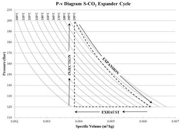
The cycle of the expander includes three optimal points: injection, expansion, and exhaust. Assumptions were made to neglect frictional losses, thermal losses through the expander itself, and steady state conditions. Figure 7 shows the ideal expansion cycle of the expander from start to finish. The cycle begins with the piston at top dead center as SCO2 is injected into the expander at 20 MPa and 200°C. This raises the pressure from 12 MPa to 20 MPa and the operating temperature of the previously expanded fluid from 90°C to 200°C within a relatively short amount of time. After the SCO2 is injected into the chamber the fluid is naturally allowed to expand, thus pushing the piston to bottom dead center. This expansion allows the pressure and temperature to drop while ideally maintaining constant enthalpy, and providing work for the system. The final leg of the cycle is a constant pressure evacuation of the piston chamber. This exhaust portion comes from the driving force done by the other side of the piston cycling through the expansion portion of the cycle. As the piston now slides back to top dead center, valves open inside the chamber allowing the SCO2 to evacuate back into the supply loop at reduced pressure and temperature of 12 MPa and 90°C. Once the expander has been built, careful testing will yield empirical data with which the theoretical results can be correlated.
4.3. Internal Heat Exchanger
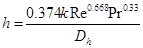
The required heat transfer area from the heat exchanger analysis led to very large length requirements for a standard counter flow concentric pipe configuration. Plate-based heat exchangers are desirable for large area requirements because of their large surface-area to volume ratio. Therefore, the compact plate heat exchanger architecture was chosen to reduce the overall size of the heat exchanger. The MATLAB code in section 3.2 was modified to arrive at a new area requirement using the plate convection correlation, h [28] given by Eqn. (18).
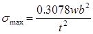
Due to the operating pressures and temperatures aluminum and copper heat transfer interfaces were not viable. The high side temperature is in the aging range of aluminum, which leads to eventual embrittlement and weakening below an acceptable level. Copper has acceptable temperature performance, but was not viable due to its low material strength. Therefore, stainless steel was selected because it provided the best compromise between strength and thermal conductivity at the operating pressure and temperature. Plate thickness was determined by calculating σmax. [34] via the relationship of Eqn. (19).
5. Conclusions
The above analysis examines the feasibility of a regenerative Rankine cycle utilizing SCO2 for waste heat recovery in small-scale systems. Initial analysis suggests that recovery from low temperature sources approximately 200°C and above is feasible with an operating efficiency of 11% given the conservative operating parameters in Table 1. Agreement between the present results and those of [11-13,15,16] has been demonstrated offering validity to the current study. Further analysis and experimental validation is required for optimal development of hardware that may be used for low flow rates. It is notable that the overall thermodynamic efficiency of the system is highly dependent on the internal heat exchanger effectiveness and it is expected that higher system efficiencies may be achieved after development and optimization of the system.
References
[1] U.S. Energy Information Administration Office of Integrated Analysis and Forecasting. Annual Energy Outlook 2010, US Department of Energy, 2010. View Article
[2] Waste Heat Recovery in Industrial Facilities: Opportunities for Combined Heat and Power and Industrial Heat Pumps. EPRI,Palo Alto, CA: 2010. View Article
[3] Waste Heat Recovery: Technology and Opportunities in U.S. Industry, BCS Incorporated, Report to U.S. DOE Industrial Technologies Program, March 2008. View Article
[4] An Inventory of Industrial Waste Heat and Opportunities for Thermally Activated Technologies, Report for Oak Ridge National Laboratory, United Technologies Research Center, 2004.
[5] V. Dostal, M.J. Driscoll, P. Hejzlar, "A Supercritical Carbon Dioxide Cycle For Next Generation Nuclear Reactors", Massachusetts Institute of Technology, Dept. of Nuclear Engineering, 2004. View Article
[6] X.R. Zhang, H. Yamaguchi, K. Fujima, M. Enomoto, N. Sawanda, "Experimental Performance Analysis of Supercritical CO2 Thermodynamics Cycle Powered by Solar Energy, Flow Dynamics", The Second International Conference on Flow Dynamics, 2006. View Article
[7] J. Sarkar, S. Bhattacharyya, "Optimization of Recompression SCO2 Power Cycle with Reheating, Energy Conversion and Management", Elsevier, 2009. View Article
[8] J. Sarkar, "Second Law Analysis of SCO2 Recompression Brayton Cycle", Energy, Elsevier, 2009. View Article
[9] S. Wright, R. Radel, M. Vernon, G. Rochau, P. Pickard, "Operation and Analysis of a SCO2 Brayton Cycle", Sandia Report, Sandia National Laboratories, 2010. View Article
[10] E.W. Lemmon, M.L. Huber, M.O. McLinden, "NIST Standard Reference Database 23: Reference Fluid Thermodynamic and Transport Properties-REFPROP", National Institute of Standards and Technology, Standard Reference Data Program, Version 9.0. View Article
[11] H. Chen, D.Y. Goswami, E. Stefanakos, "A Review of Thermodynamic Cycles and Working Fluids for the Conversion of Low-Grade Heat", Renewable and Sustainable Energy Reviews, Vol. 14, 2010, pp. 3059-3067. View Article
[12] E. Cayer, N. Galanis, M. Desilets, H. Nesreddine, P Roy., "Analysis of a Carbon Dioxide Transcritical Power Cycle Using a Low Temperature Source", Applied Energy, Vol. 86, 2009, pp. 1055-1063. View Article
[13] H. Tou, "Parametric Analysis of a Reheat Carbon Dioxide Transcritical Power Cycle Using a Low Temperature Heat Source", 2011 2nd International Conference on Environmental Engineering and Applications, IPCBEE, Vol. 17, 2011, IACSIT Press, Singapore. View Article
[14] M. Kulhanek, V. Dostal, "Thermodynamic Analysis and Comparison of Supercritical Carbon Dioxide Cycles", Proceedings of the Supercritical CO2 Power Cycle Symposium, May 24-25, 2011, Boulder, Colorado. View Article
[15] Y. Chen, "Novel Cycles Using Carbon Dioxide as Working Fluid - New Ways to Utilize Energy from Low-Grade Heat Sources, Thesis, School of Industrial Engineering and Management", Dept. of Energy Technology, Division of Applied Thermodynamics and Refrigeration, Stockholm, Sweden, May 2006. View Article
[16] Y. Chen, P. Lundqvist, A. Johansson, P. Platell, "A Comparative Study of the Carbon Dioxide Transcritical Power Cycle with an Organic Rankine Cycle with R123 as Working Fluid in Waste Heat Recovery", Applied Thermal Engineering, Vol. 26, 2006, pp. 2142-2147. View Article
[17] H. Gao, C. Liu, C. He, X. Xu, S. Wu, Y. Li, "Performance Analysis and Working Fluid Selection of a Supercritical Organic Rankine Cycle for Low Grade Waste Heat Recovery", Energies, 2012, 5, 3233-3247 View Article
[18] J. Wang, S. Zhixin, Y. Dai, S. Ma, "Parametric Optimization Design for Supercritical CO2 Power Cycle Using Genetic Algorithm and Artificial Neural Network", Applied Energy, Vol. 87, 2010, pp. 1317-1324. View Article
[19] M. Persichilli, A. Kacludis, E. Zdankiewicz, T. Held "Supercritical CO2 Power Cycle Developments and Commercialization: Why SCO2 Can Displace Steam", Presented at Power-Gen India & Central Asia 2012, 19-21 April, 2012, Pragati Maidan, New Delhi, India View Article
[20] A. Kacludis, S. Lyons, D. Nadav, E. Zdankiewicz, "Waste Heat to Power (WH2P) Applications Using a Supercritical CO2 Based Power Cycle", presented at Power-Gen Intl. 2012, Dec. 11-13, 2012, Orlando, FL, USA. View Article
[21] X.R. Zhang, H. Yamaguchi, K. Fujima, M. Enomoto, N. Sawada, "Theoretical Analysis of a Thermodynamic Cycle for Power and Heat Production Using Supercritical Carbon Dioxide", Energy, Vol 32, 2007, pp. 591-599. View Article
[22] H. Yamaguchi, X.R. Zhang, K. Fujima, M. Enomoto, N. Sawada, "Solar Energy Powered Rankine Cycle Using Supercritical CO2", Applied Thermal Engineering, Vol. 26, 2006, pp. 2345-2354. View Article
[23] S. Besarati, D.Y. Goswami, "Analysis of Advanced Supercritical Carbon Dioxide Power Cycles with a Bottoming Cycle for Concentrating Solar Power Applications", IMECE2013-63753, Proceedings of the ASME Intl. Mechanical Engineering Congress & Exposition, Nov. 15-21, 2013, San Diego, CA, USA. View Article
[24] A. Sabau, H. Yin, L. Qualls, J. McFarlane, "Investigations of Supercritical CO2 Rankine Cycles for Geothermal Power Plants", Proceedings of the Supercritical Power Symposium, May 24-25, 2011, Boulder, Colorado. View Article
[25] Y. Chen, P. Lunqvist, P. Platell "Theoretical Research of Carbon Dioxide Power Cycle Application in Automobile Industry to Reduce Vehicle's Fuel Consumption", Applied Thermal Engineering, Vol. 25, 2005, pp. 2041-2053. View Article
[26] L. Zhang, T. Akiyama "How to recuperate industrial waste heat beyond time and space" International Journal of Exergy, 2009; 6 (2): 214. View Article
[27] F. Incropera, D. DeWitt, "Fundamentals of Heat and Mass Transfer", 6th edition, John Wiley & Sons Inc., 2006. View Book
[28] T. Kuppan, "Heat Exchanger Design Handbook", 1st edition, Dekker, 2000. View Book
[29] J-E. Cha, T-H. Lee, J-H. Eoh, S-H. Seong, S-O. Kim, D-E. Kim, M-H. Kim, T-W. Kim and K-Y. Suh "Development of a Supercritical CO2 Brayton Energy Conversion System Coupled with a Sodium Cooled Fast Reactor", Seoul: Seoul National University, 2009. View Article
[30] Y. Chen, "Novel Cycles Using Carbon Dioxide as Working Fluid: Licentiate Thesis", School of Industrial Engineering and Management, 2006. View Article
[31] H. Huff, "CO2 Compressor - Expander Analysis", College Park: Air-Conditioning and Refrigeration Technology Institute, 2003. View Article
[32] S.L. Dixon, C.A. Hall, "Fluid Mechanics and Thermodynamics of Turbomachinery", Burlington: Elsevier, 2010. View Book
[33] M.O. Khan, "Basic Practices in Compressors Selection", International Compressor Engineering Conference, 1984. View Article
[34] W.C. Young, R.G. Budynas, "Roark's Formulas for Stress and Strain", 7th edition, McGraw-Hill, 2002. View Article