Advances in Renewable Energy (ARE)

Volume 2, Year 2015 - Pages 1-10
DOI: TBD
Performance Analysis of Hydrokinetic Turbine Blade Sections
Abdullah Muratoglu1,2, M. Ishak Yuce2
1Batman University, Civil Engineering Department
72100, Batman, Turkey
abdullah.muratoglu@batman.edu.tr
2Gaziantep University, Civil Engineering Department
27310, Gaziantep, Turkey
yuce@gantep.edu.tr
Abstract - Hydrokinetic turbines are recently developed renewable energy harnessing devices which convert the kinetic energy of rivers, tidal currents and waves into electricity. The blade sections (hydrofoil) of in-stream hydrokinetic energy converters are very important which have a great impact on the turbine performance. Various studies have been conducted on horizontal axis wind turbine blade sections. However the hydrokinetic turbine blade profiles are poorly investigated. The aim of this study is to apply a numerical performance analysis on pre-developed blade sections to be used hydrokinetic turbines. The lift, drag and pressure coefficients of various NACA, NREL and RISØ hydrofoils were studied. The most suitable blade sections were pointed out considering high lift/drag ratio and low cavitation criteria.
Keywords: Hydrokinetic turbine, Hydrofoil, Blade section, JavaFoil, Numerical analysis.
© Copyright 2015 Authors - This is an Open Access article published under the Creative Commons Attribution License terms. Unrestricted use, distribution, and reproduction in any medium are permitted, provided the original work is properly cited.
Date Received: 2014-12-29
Date Accepted: 2015-12-07
Date Published: 2015-12-23
Nomenclature
A Projected area
b Span length
c Chord length
Cd Drag coefficient
Cl Lift coefficient
Cl/Cd Lift/drag ratio
Cm Pitching moment coefficient
Cp Pressure coefficient
Cp,min Minimum pressure coefficient
FD Drag force
FL Lift force
Mp Pitching moment
P Pressure
P0 Local pressure
P∞ Free stream static pressure
Pv Vapor pressure
q Dynamic pressure
Re Reynolds number
U Velocity
Ucavitate Cavitation velocity
Urel Relative velocity
α Angle of attack
ρ Density
σ Cavitation number
1. Introduction
Hydrokinetic turbines are electromechanical devices that convert kinetic energy of flowing water into electricity. The cross-sections of hydrokinetic turbine blades are known as hydrofoils. The turbine blades are used to produce a lift force in order to rotate and extract the optimum power from the system. Each blade of a hydrokinetic turbine is designed from one or more types of hydrofoils. The efficiency and performance of the rotor is mostly dependent on the shape of hydrofoil used. Generally, the thin hydrofoils deliver more efficiency than the thick ones. However, from the structural strength point of view, the thickness of the cross-sections of the hydrofoils near the blade root should be increased. The design thickness of the blade sections depends also on the span length and the hydrodynamic requirements. In large rotor diameter turbines, relatively thicker hydrofoils should be employed in order to accomplish structurally strong blades. Owing to the high density of water, compare to the density of air, the hydrodynamic forces acting on hydrokinetic turbines are greater than the aerodynamic forces on wind turbines. Therefore the blade sections of hydrokinetic turbines should be relatively thicker than that of wind turbines [1].
The main goal of blade and wing design is to increase the lift coefficient and decrease the drag and pitching moment coefficients [2]. Cavitation is the biggest restriction in choosing a hydrofoil for a hydrokinetic turbine rotor. Thin blade sections [1] especially the hydrofoils that are used at the blade tip are more susceptible to cavitation. In order to design a high performance rotor, the cavitation number should be as low as possible while the lift coefficient and the lift to drag (Cl/Cd) ratio should be as high as possible.
Numbers of institutions are making special efforts to perform theoretical and experimental studies in order to develop foils. NASA (U.S. National Aeronautics and Space Administration), NREL (U.S. National Renewable Energy Laboratory), Gottingen, Eppler, Wortmann and RISØ are among the most well-known foil developers.
In the present study, the performance analyses have been conducted on several NACA, NREL and RISØ hydrofoils which will be used in hydrokinetic turbines. The blade sections have been selected among the widely used high performance wind turbine airfoils. The numerical analyses have been performed by using JavaFoil [3] code.
2. Hydrofoil Terminology
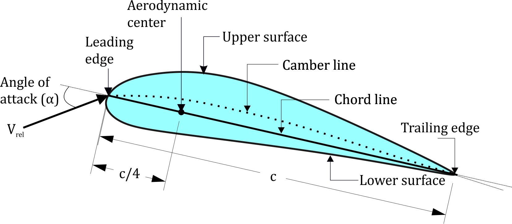
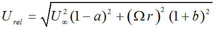
A detailed representation of a hydrofoil and its terminology is given in Figure 1. A hydrofoil principally has an upper and a lower surface. In most of the hydrofoils, the curvature of the upper surface is higher than that of the lower surface. The intersection points of both surfaces at the forward and rearward regions are known as leading and trailing edges, respectively. The flat line connecting the leading and the trailing edges is called chord line; its length is denoted by c. The line which is the locus of the mid-points between the upper and the lower surfaces of a hydrofoil is known as camber line. The camber of a hydrofoil is defined as the vertical distance between the chord line and the camber line, the greatest value of that distance is called the maximum camber. The distance between the upper and the lower surfaces measured perpendicular to the chord line is the thickness of the hydrofoil. The angle of attack, which is represented by α is the geometric angle between the relative velocity vector, Urel and the chord line. The span is the perpendicular length of the blade relative to the cross section [4].
Hydrofoils are characterized by the coordinates of both the upper and lower surfaces. They are generally numbered by using a few parameters such as the maximum thickness, the maximum camber, the position of the maximum thickness, the position of the maximum camber and the nose radius [5].
3. Literature Review
Various studies have been performed to provide a suitable blade section for horizontal axis hydrokinetic turbines. Ahmed [1] conducted a general assessment for blade sections to be used in hydrokinetic turbines. Grogan at. al. [6] used RISØ-A family of blade sections to design a 12 m long composite tidal turbine blade. Lawson and Sale [7] used NACA 63(1)-424 foil to model a horizontal axis hydrokinetic turbine rotor of 20 m diameter. In a study carried out by Jonkman and Musial [8], NACA44XX and RISØ-A1-XX type of hydrofoil families were employed and RISØ foils were found more feasible than NACA foils to be used in stall regulated turbines. Grasso [9] designed a new hydrofoil named G-Hydra-B which provided better performance compare to NACA 4418 and DU96-W-180 blade sections. Batten at. al. [10] used NACA 63-8xx profiles to predict a hydrokinetic turbine rotor performance and reported the cavitation tests for NACA 63-815 and NACA 63-215. NACA 63-815 hydrofoil which has high camber and high lift coefficient was found to be exposed to less cavitation for high lift coefficients. Molland at. al. [11] evaluated lift and drag characteristics and applied cavitation tunnel experimental and numerical panel codes on NACA 6615, 63-215 and 63-815 hydrofoils. NACA 63-815 profile was found to have higher performance than the other one to be used in water environment. Cairo at. al. [12] designed a new hydrofoil (GT1, Cl/Cd=122) by modifying S805 (Cl/Cd=88) which has high lift coefficient and low cavitation number [1]. Ahmad [1] has found RISØ-A1-24, S805, S814 and GT1 hydrofoils feasible to be used in hydrokinetic turbine blades.
4. Methodology
4. 1. Hydrodynamic Forces
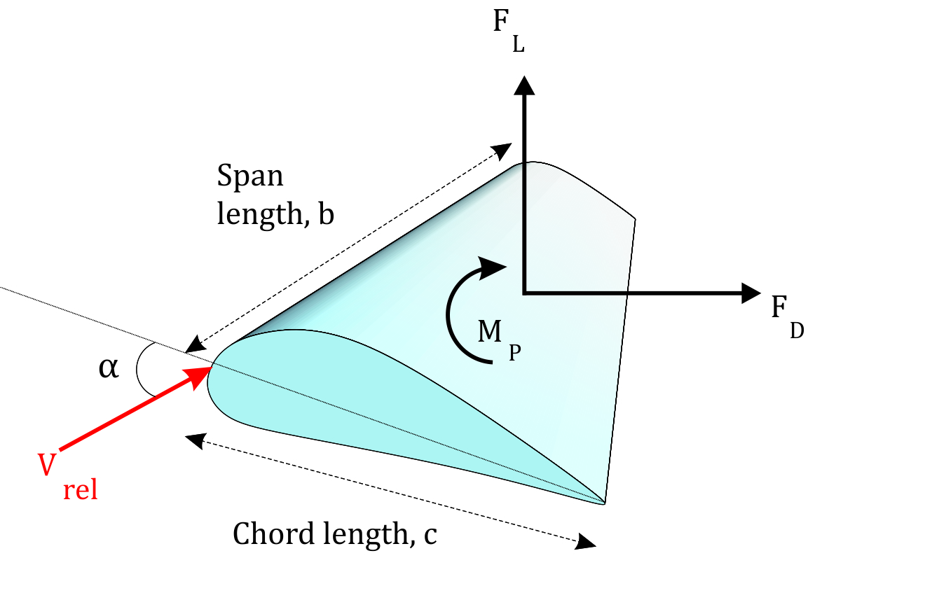
A hydrofoil submerged in a stream flow is subjected to various forces due to pressure and velocity changes and the viscosity of the fluid. The representation of the forces on a hydrofoil section is given in Figure 2. The forces exerted on the hydrofoil are drag force, FD, lift force, FL and pitching moment, MP. Drag force is the force that is exerted on the body by the fluid, parallel to the flow direction. The viscous friction and the unequal pressures at the hydrofoil surfaces bring up the drag force [4]. When the fluid moves over the hydrofoil, the velocity of the fluid particles at the upper surface become higher than that of lower surface due to the camber and the angle of attack. High velocity generates a low pressure zone at the upper surface of the hydrofoil while low velocity at the lower surface produces a high pressure zone. Unequal pressure distribution between two surfaces of hydrofoil creates the lift force. The direction of the lift force is normal to the chord line. Similarly, the pitching moment originates as a function of the integral of the moments of pressure forces over the surfaces of the foil. The application point of these three loads on the hydrofoil is generally accepted to be at c/4 distance from the leading edge on the chord line [13]. The hydrodynamic loads vary with the flow velocity, density of the fluid and the frontal area as well as the size, the shape and the orientation of the body [14]. Instead of using many parameters in the equations related to the orientation and the position of the body, lift, drag and pitching moment coefficients are employed.
Lift and drag forces and pitching moment can be formulated as below;
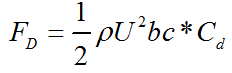
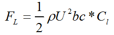
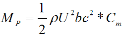
where; FD is drag force, FL is lift force, MP is pitching moment, b is the span length, c is the chord length, ⍴ is the flow density, A is the projected area of hydrofoil, Cd, Cl and Cm are drag, lift and pitching moment coefficients, respectively.
4. 2. The Effect of Reynolds Number and Angle of Attack
The Reynolds number (Re) has a significant importance on the behavior of the foils. When Re decrease, the relative magnitude of the viscous forces become more than the inertial forces. Thus, surface friction and pressure gradients increases. This process results increase in the drag coefficient and reduction in the lift coefficient [4]. In symmetrical foils, the lift coefficient is zero at zero angle of attack (α). At low angle of attacks, the lift coefficient is small and increases linearly with increasing the angle of attack. Cl can be increased at low α by using a cambered foil [4], [15]. After α reaches a specific point an abrupt decline is observed in the foil performance and then it stalls. This point is known as maximum lift. The lift behavior of the foil is more or less the same for negative angle of attacks [4], [15]. Generally, the drag coefficient increases with increase in angle of attack.
4. 3. JavaFoil as a Numerical Foil Analysis Tool and its Verification
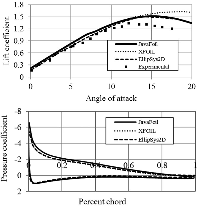
Experimental analyses of blade sections via water and wind tunnel tests are rather difficult to conduct. Several numerical analyses codes were developed providing a theoretical base for the foil analyses. JavaFoil [3], XFOIL [16] and EllipSys2D are among two dimensional foil analysis tools. In this study JavaFoil code was used. JavaFoil [3] is a simple foil analysis code which employs traditional methods to analyze the section under subsonic flow conditions. The main purpose of the code is to determine the lift, drag and pitching moment coefficients of the foil. Additionally, the velocity and pressure coefficient distributions along surface can be obtained [17].
The analyses are made by calculating the velocity distribution along the surface using higher order panel method (linearly varying vorticity distribution) which is based on Bernoulli Equation. The flow behavior on the foil surface and boundary layer analyses are applied by using differential equations [17]. The analyses can be made for the desired angle of attack and Reynolds number. JavaFoil code provides good performance comparing with experimental results and other numerical analysis tools. The graph for the verification of JavaFoil’s performance relative to the experimental and numerical results is given in Figure 3.
4. 4. Cavitation Problem
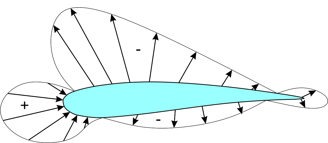
Cavitation on water turbines mainly depends on the pressure coefficient of the blade section. Pressure coefficient (Cp) is a non-dimensional parameter which shows the relative pressure on the surfaces of the foil. The typical distribution of pressure on the upper and lower surfaces of a foil is given in Figure 4. The coefficient of pressure is equated as;
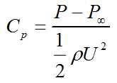
For simplification, the pressure coefficient can be written as the function of velocity;

where; P is the local static pressure, P∞ is the free stream static pressure, U is the fluid particle’s velocity.
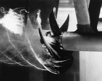
When the pressure inside the water flow falls below the vapor pressure of the fluid, local boiling occurs and water bubbles develop. Under this condition, the bubbles grow and produce shock waves, noise and some other dynamic effects. This situation results the cavitation on the turbine blades. Cavitation significantly damages the blades, decreases the performance and sometimes causes failure. Especially the parts of turbines, which move with high speed such as blade tips, are subjected to more cavitation [19], [20]. Cavitation is one of the biggest constraints to be considered while modelling a water turbine. It should be taken into account in the designing stage. Figure 5 illustrates the cavitation of a propeller inside a water tunnel.
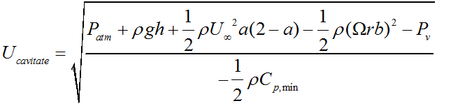
The equations required to calculate the existence and the amount of cavitation in any section of a turbine blade is given below [9], [21];
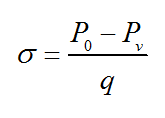
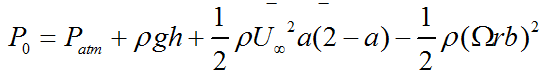
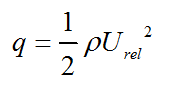
where, P0 is the local pressure, Pv is the vapor pressure and q is the dynamic pressure.
If the absolute value of pressure
coefficient becomes greater than the cavitation number, (![]() ), the blade instigates cavitation [1], [11]. Likewise, the blade does not expose to cavitation until cavitation velocity (Ucavitate) exceeds the relative velocity (Urel) [21].
), the blade instigates cavitation [1], [11]. Likewise, the blade does not expose to cavitation until cavitation velocity (Ucavitate) exceeds the relative velocity (Urel) [21].
5. Performance Analysis
The performance of NACA, NREL and RISØ hydrofoils have been numerically analyzed and compared with each other, from the hydrodynamics point of view, using the numerical code named JavaFoil. In the investigations the Calcfoil stall model and the Eppler standard transition models have been used. The Reynolds number was taken to be 1x10⁶ in the analyses. The transition of the upper and the lower surfaces for the calculation of pressure coefficients has been taken as 100%. The lift and drag coefficients ratios (Cl/Cd) and the pressure coefficients for each group of hydrofoils have been detailed.
5. 1. NACA Hydrofoils
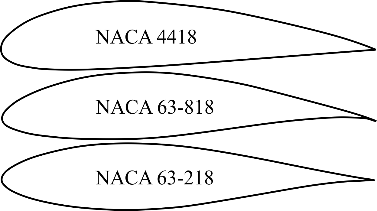
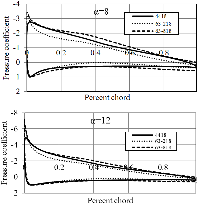
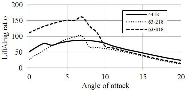
NASA sections (previously known as NACA) are perhaps, the most famous foils for various applications from aircraft wings to wind or hydrokinetic turbines. NACA 44 and 63 series of foils (Figure 6) are among the commonly used blade sections [22], since they are known for their characteristics of stall delay and less sensitive to leading edge roughness than other foil families [7]. Therefore, plenty of facts and analyses have been published for these blade sections to be used in wind and hydrokinetic turbines. Correspondingly, in this research NACA 4418, NACA 63-218 and NACA 63-818 hydrofoils were analyzed. NACA 4418 hydrofoil is 18% thick, having 4% camber at the 40% of the chord. NACA 63-218 and NACA 63-818 blade sections are classified as NACA 6 digit foil series. NACA 6 digit blade sections have been developed by using advanced mathematical methods. Both hydrofoils are designed with 18% thickness at 30% of the chord from the leading edge.
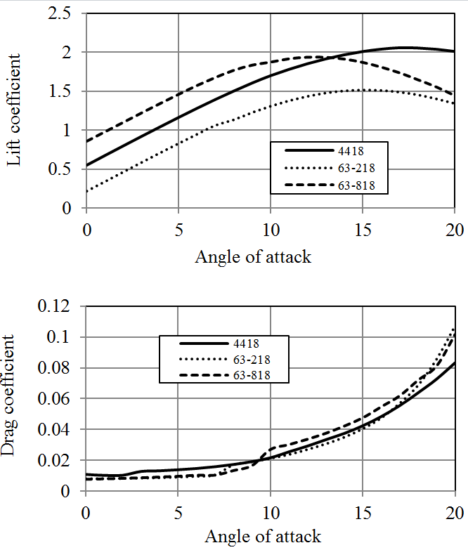
JavaFoil analysis results of these hydrofoils are given in Figures 7-9. Both NACA 63-218 and NACA 4418 hydrofoils have similar Cl/Cd ratios however NACA 63-818 section provides much higher Cl/Cd ratio. On the other hand, the average pressure coefficient of NACA 63-818 is more than the other two foils which shows that, it is more susceptible to cavitation. All these NACA blade sections have relatively higher pressure coefficients. Consequently, high stall angles of NACA 4418 and 63-218 makes them infeasible to be employed in stall regulated turbines.
5. 2. NREL Hydrofoils
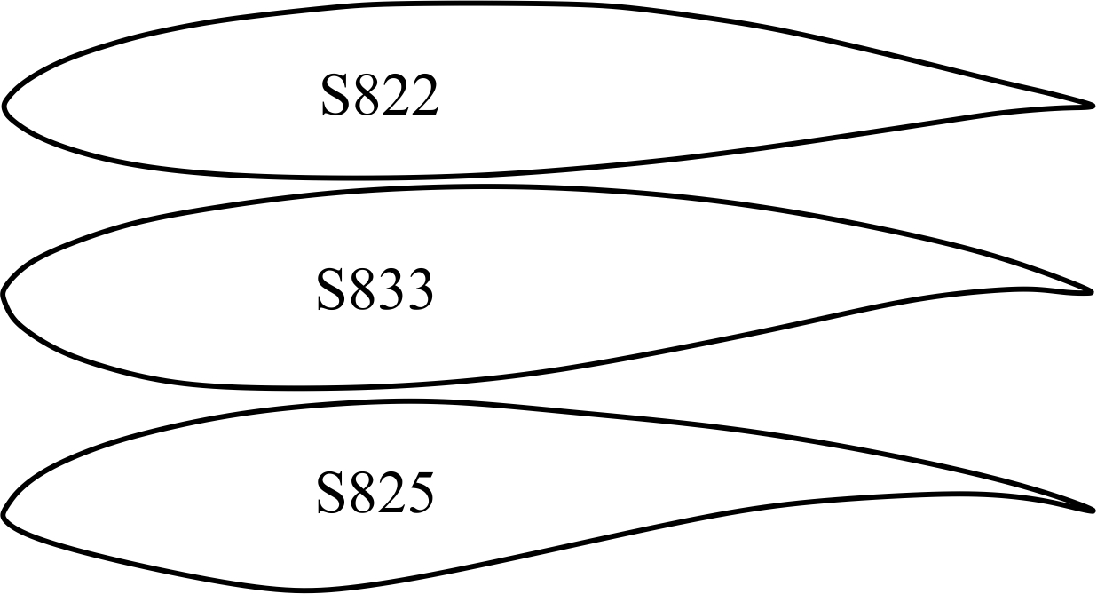
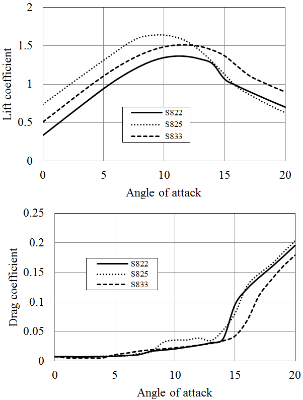
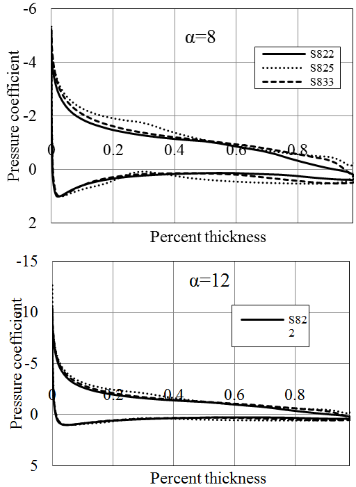
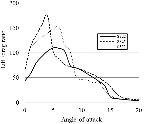
NREL (U.S. National Renewable Energy Laboratory) blade sections have been specially developed to be used in horizontal axis wind turbines. In these blade sections, the roughness effects can be reduced by half relative to that are developed for aircrafts [22]. The performance analyses have been performed on the blade sections from three different foil families of NREL [23]-[25], namely S822, S825 and S833 (Figure 10). S822 is a 16 % thick foil developed for the tip regions of 3-10 m diameter stall regulated turbines [23]. S825 is devised for 20-40 meter variable speed, variable pitch horizontal axis turbines having a thickness of 18 % [25]. S833 have been designed for the primary regions of 1-3 meter variable speed, variable pitch turbines with a thickness of 18 % [24].
Both S825 and S833 profiles deliver high lift coefficients and Cl/Cd ratios. The highest Cl/Cd ratio is provided by S833 blade section which was found to be above 150 for Re=1x10⁶. On the other hand, the pressure coefficient calculated for S825 profile is the highest exceeding 12 at ɑ=12ᵒ (Figures 11-13). The cavitation number of this section will be more than the other two profiles especially when it is used at the tip regions of a blade. S822 and S833 hydrofoils have more or less similar pressure coefficients (approximates 10 at ɑ=12ᵒ) which is lower than that of S825. The most suitable hydrofoil in this class is thought to be S833, having quite high Cl/Cd ratio and relatively lower pressure coefficient. However, the pressure coefficient is still high relative to the NACA and RISØ sections. The further comparison of NREL, RISØ and NACA hydrofoils are given in section 6.
5. 3. RISØ Hydrofoils
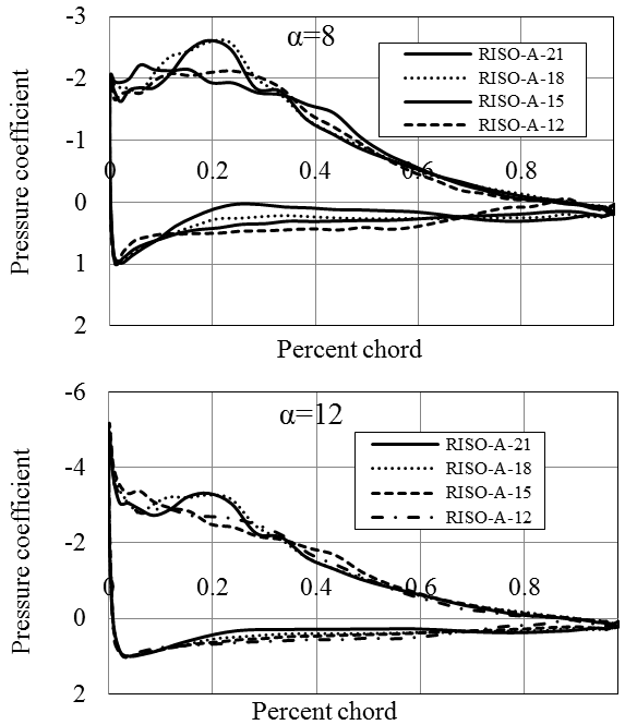
RISØ-A family of foils were developed and optimized at RISØ National Laboratory (Denmark) in order to be employed in wind turbines [18]. This group of blade sections is characterized by their sharp nose (Figure 14) [26]. They have quite low pressure coefficient providing high performance and low cavitation in hydrokinetic turbines. The design stall angle for these hydrofoils is 10ᵒ [26]. The cluster has been developed to have seven foils between 30 to 12 % thicknesses. In the present study, 4 blade sections with thicknesses of 21, 18, 15 and 12 % were analyzed. The technical details of RISØ foils are given in Table 1.
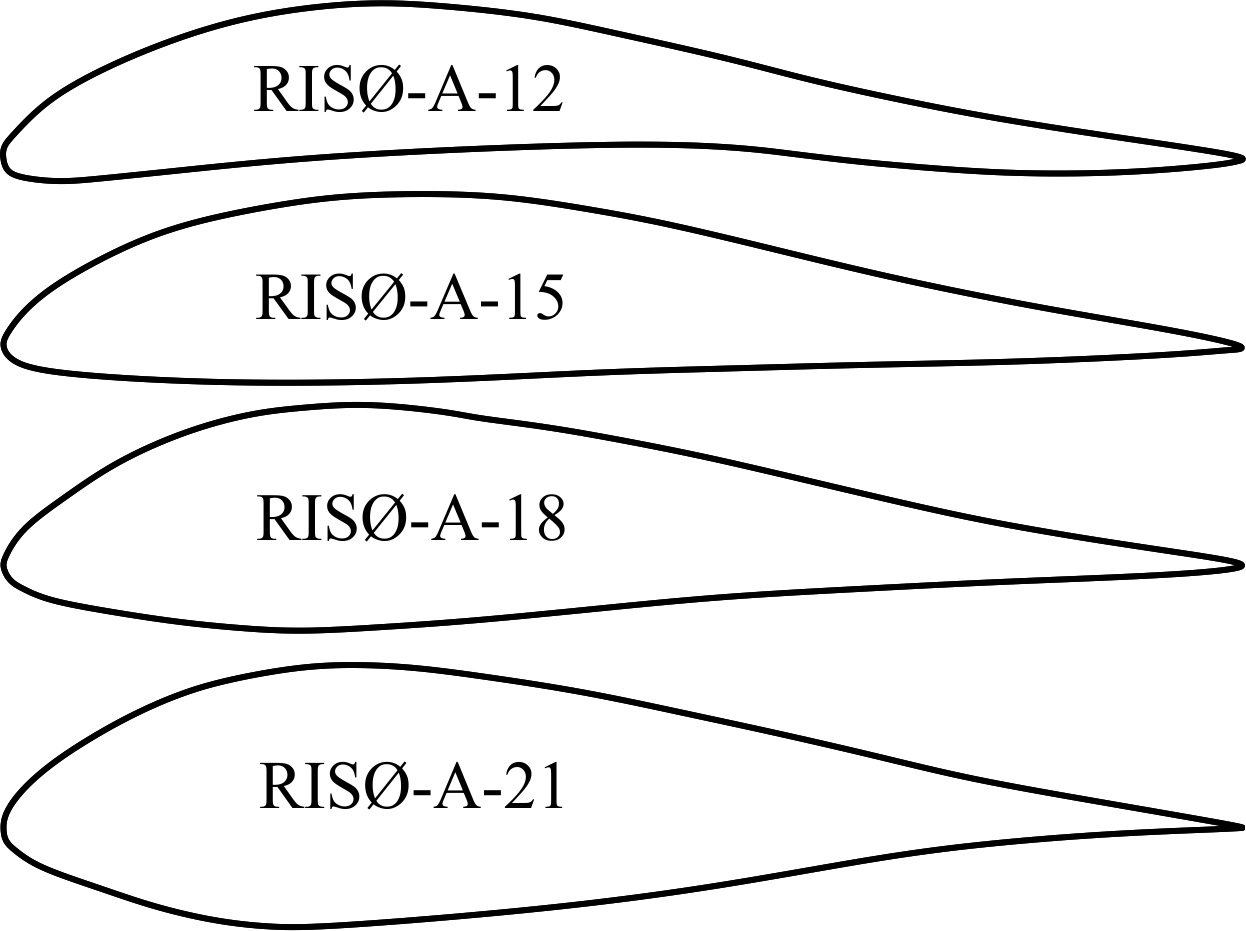
Table 1. Technical details of RISO-A hydrofoils (Analyzed in JavaFoil, Re=1x10⁶).
| Blade section | % Thickness | % Camber | Stall angle | Max. Cl |
| RISO-A-12 | 0.0 | 6.5 | 10ᵒ | 1.618 |
| RISO-A-15 | 0.5 | 4.7 | 10ᵒ | 1.712 |
| RISO-A-18 | 4 | 10ᵒ | 1.756 | |
| RISO-A-21 | 1.0 | 2.5 | 10ᵒ | 1.678 |
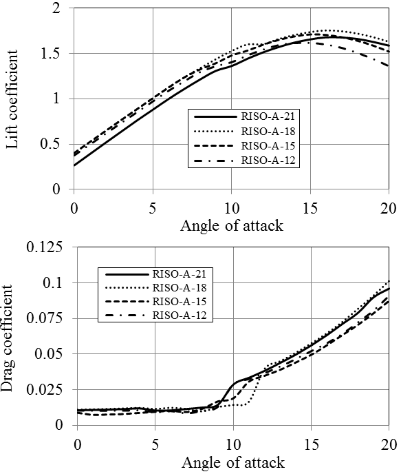
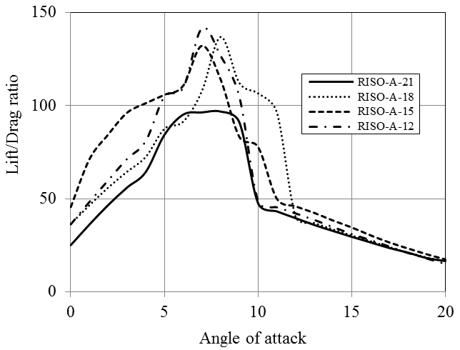
All four types of the blade sections have similar lift and drag coefficients. The hydrodynamic performance and pressure coefficient diagrams for RISØ foil family is given in Figures 15-17. RISØ A-21, 18 and 15 profiles provides nearly the same Cl/Cd ratios which approximate 150 for Re=1x10⁶. RISØ-A-21 has lower Cl/Cd ratio (below 100) than the other three sections. This hydrofoil is more suitable to be used at the blade root due to its thickness of 21%. All four blade sections deliver extremely low pressure coefficients all around the profile especially at the leading and trailing edges. As a different condition, they provide relatively higher pressure coefficient close to 20 % of the chord.
6. Discussion and Conclusion
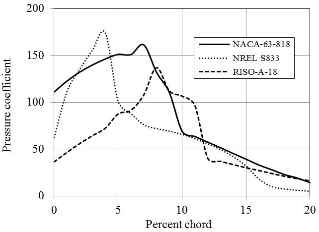
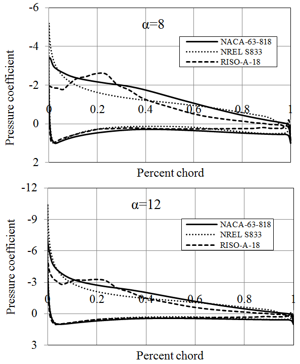
A number of hydrofoils from NACA, NREL and RISØ have been investigated from hydrodynamics point of view. The discussions and the outcomes stated here are based solely on the hydrofoils analyzed within the frame work of this particular study; they do not cover the other foils of the groups mentioned above. The comparison of Cl/Cd ratio and pressure coefficients of NACA 63-818, NREL S833 and RISØ-A-18 blade sections are given in Figures 18 and 19 respectively. Each of these blade sections have 18 % thickness and provides high hydrodynamic performance regarding the family they belong.
It is important for hydrokinetic turbine blade sections to provide a high lift coefficient with a large Cl/Cd ratio while keeping the cavitation as minimum as possible. A hydrofoil incepts cavitation when the absolute value of the pressure coefficient, Cp, exceeds the cavitation number, σ. Therefore the pressure coefficient is one of the key parameters in order to select the suitable hydrofoil [27].
According to the analyses results obtained by JavaFoil, NACA-63-818 blade section delivers a Cl/Cd ratio which is more than 150 for Re=1x10⁶ (Figure 9). The other two hydrofoils of NACA family have considerably lower lift characteristics. NREL hydrofoils, namely S825 and S833 provide larger lift force than S822. In addition NREL S822, S825 and S833 hydrofoils have substantially high pressure coefficients. Generally, NACA blade sections provide lower pressure coefficient than those of NREL. Utilization of some of NREL blade sections in hydrokinetic turbines can cause considerably high cavitation, especially at the leading edges. While RISØ blade sections of A-18, A-15 and A-12 generate high lift forces, RISØ-A-21 hydrofoil does not produce a high lift force in water environment. RISØ-A-21, which is a 21% thick hydrofoil, can be utilized at the blade root. The other hydrofoils can be employed from primary blade section to the tip of the blade according to their thicknesses. RISØ-A foils family delivers exceptionally low pressure coefficients compare to NACA and NREL hydrofoils (Figure 19). Therefore, it could be said that RISØ-A hydrofoils are reasonably resistant to cavitation [8].
Consequently, both NACA 63 and RISØ-A blade sections provide good performance in order to be employed in hydrokinetic turbines. However, majority of NACA foils are not suitable to be used in hydrokinetic turbines because of their poor stall characteristics, low structural efficiency near the hub, and conflicting performance at different Reynolds numbers and low performance due to roughness [1]. RISØ-A hydrofoils were specially designed for stall-regulated turbines having an ideal power curve with a good efficiency and supplying nearly a constant power output with the velocities above the rated speed [8], [28].
References
[1] M. R. Ahmed, "Blade sections for different turbine and tidal current turbine applications-current status and future challenges," International Journal of Energy Research, vol. 36, no. 7, pp. 829-844, 2012. View Article
[2] M. S. Genç, "Kanat profilleri etrafındaki düşük Reynolds sayılı akışın kontrolü ve aerodinamik performansın incelenmesi," Ph.D. Dissertation, Natural and Applied Sciences Institute, Erciyes University, 2009.
[3] JAVAFOIL-Analysis of airfoils [Online]. View Article
[4] J. F. Manwell, J. G. Mcgowan and A. L. Rogers, Wind energy explained: theory design and application, Wiltshire: John Wiley & Sons Ltd., 2009. View Book
[5] I. Kroo. (2007). Applied Aerodynamics: a digital textbook [Online]. View Article
[6] D. M. Grogan, S. B. Leen, C. R. Kennedy and C. M. Ó. Brádaigh, "Design of composite tidal turbine blades," Renewable Energy, vol. 57, pp. 151-162, 2013. View Article
[7] M. J. Lawson, Y. Li and D. C. Sale, "Development and verification of a computational fluid dynamics model of a horizontal-axis tidal current turbine," in ASME 2011 30th International Conference on Ocean, Offshore and Arctic Engineering, Rotterdam, 2011. View Article
[8] J. Jonkman and W. Musial, "Hydrodynamic optimization method and design code for stall-regulated hydrokinetic turbine rotors," in ASME 28th International Conference on Ocean, Offshore, and Arctic Engineering, Honolulu, 2009. View Article
[9] F. Grasso, "Design and optimization of tidal turbine airfoil," Journal of Aircraft, vol. 49, no. 2, pp. 636-643, 2012. View Article
[10] W. M. J. Batten, A. S. Bahaj, A. F. Molland and J. R. Chaplin, "The prediction of hydrodynamic performance of marine current turbines," Renewable Energy, vol. 33, no. 5, pp. 1085-1096, 2008. View Article
[11] A. F. Molland, A. S. Bahaj, J. R. Chaplin and W. M. J. Batten, "Measurements and predictions of forces, pressures and cavitation on 2-D sections suitable for marine current turbines," in Proceedings of the Institution of Mechanical Engineers, Part M: Journal of Engineering for the Maritime Environment, 2008. View Article
[12] D. P. Cairo, U. Maisto, F. Scherillo, S. Melone and F. Grasso, "Horizontal axis tidal current turbine: numerical and experimental investigations," in Proceeding of Owemes (Offshore Wind and other Marine Renewable Energies in Mediterranean and Europenan Seas), Civitavecchia, 2006. View Article
[13] M. O. L. Hansen, Aerodynamics of wind turbines, Routledge, 2007. View Book
[14] Y. A. Cengel and J. M. Cimbala, Fluid Mechanics Fundamentals and Applications, New York: Mcgraw-Hill, 2006. View Book
[15] P. Jain, Wind Energy Engineering, McGraw-Hill, 2011. View Book
[16] M. Drela. Subsonic Airfoil Development System [Online]. View Article
[17] M. Hepperle. (2011). JAVAFOIL User’s Guide [Online]. View Article
[18] F. Bertagnolio, N. Sørensen, J. Johansen and P. Fuglsang, Wind turbine airfoil catalogue, Roskilde: Pitney Bowes Management Services, 2001. View Book
[19] R. F. Nicholls-Lee, S. R. Turnock and S. W. Boyd, "Simulation based optimization of marine current turbine blades," in 7th International Conference on Computer and IT Applications in the Maritime Industries, Liège, 2008. View Article
[20] C. T. Crowe, D. F. Elger, B. C. Williams and J. A. Roberson, Engineering Fluid Mechanics, Wiley, 2008. View Book
[21] S. H. Person, "Composite rotor design for a hydrokinetic turbine," Thesis Projects, Mechanical Engineering, University of Tennessee, Knoxville, 2009. View Article
[22] J. L. Tangler and D. M. Somers, "NREL airfoil families for HAWTs," National Renewable Energy Laboratory, Golden, Technical Report, NREL/TP--442-7109, 01, Jan. 1995. View Article
[23] D. M. Somers, "The S822 and S823 airfoils," National Renewable Energy Laboratory, Golden, Subcontractor Report, NREL/SR-500-36342, Jan. 2005. View Article
[24] D. M. Somers, "The S833, S834 and S835 airfoils, NREL," National Renewable Energy Laboratory, Golden, Subcontractor Report, NREL/SR-500-36340, Aug. 2005. View Article
[25] D. M. Somers, "The S825 and S826 airfoils," National Renewable Energy Laboratory , Golden, Subcontractor Report, NREL/SR-500-36344, Jan. 2005. View Article
[26] S. D. Kristan and P. Fuglsang, Design of wind turbine airfoil family RISØ-a-XX, Roskilde: Risø National Laboratory, 1998. View Book
[27] M. I. Yuce and A. Muratoglu, "Hydrokinetic energy conversion systems, a technology status review," Renewable and Sustainable Energy Reviews, vol. 43, pp. 72-82, 2015. View Article
[28] A. Muratoglu, "Design and simulation of a riverine hydrokinetic turbine," Ph.D. Dissertation, Civil Engineering, Gaziantep University, Turkey, 2014.